
A complete process, from start to finish.
R4: interchangeable spray, braced overhead C-Track, robot-operated target covers and captured cleaning. Run all 55 steps, including upper-surface access.
Covered during wet / dusty operations. Open only after the clean-release condition.
Final upper-surface fit is unresolved in the existing 3.3 m booth. Gold roof extension shows a 4.1 m planning option, not approved construction. C-Track line of sight and measurement volume need OEM validation through the complete path. Motion and waiting periods are compressed for review. Functional pose interpolation is not a released robot trajectory; joint continuity, speeds and exact-CAD collision checks remain engineering work. Robot geometry is ABB-based; part, fixtures and peripheral equipment are concept models. This display is not a measured trial result or an exact-CAD collision release.
Prove the process before building the production cell.
Understand the actual part
Measure the uncoated composite surface. Establish a stable fixture datum and identify edges, chamfers, occlusions and unsupported honeycomb regions.
Control coating build
Apply the coating, correlate pre/post geometry with a qualified direct reference, and develop the 1.0 / 1.5 mm target-zone process.
Correct and verify
Remove approved excess using compliant sanding, protect thin and invalid regions, then clean and remeasure. Record process and cycle evidence.
AETEC in-house POC
1.4 m customer samples. Reserve at least 3.6 m clear height as a study allowance; site survey required. 1,200 mm starting robot mount plus guided travel (about 851 mm sampled POC travel), adapted vertical table, removable aluminium fixture and prototype protected tool / metrology stations.
Develop scanning repeatability, coating build per pass, force / abrasive settings, cleaning release and thickness correlation. Use suitable existing plant and temporary equipment.
Final DSO cell
2.1 m workpiece study. Booth A is 4.2 W × 4.6 D × 3.3 H m (existing). Open-front connected base approximately 3.7 × 3.35 m. Robot mount starts at 1,200 mm above floor, with a guided vertical axis. Normal top scanning of the 2.1 m part exceeds the existing 3.3 m booth height; the gold 4.1 m envelope is an unapproved top-access study.
Retain common fixture, docking, tool and protection interfaces. Engineer the production frame, plant, services and control architecture using the POC evidence.
Robot selection
Option 1: ABB PoWa 20, 20 kg, with the user-specified ATEX-certified protective package. Design includes supply/purge interfaces, pressure monitoring and package-ready inhibit. The certificate number, exact covered configuration and installation conditions belong in the supplier release dossier.
Option 2: ABB IRB 5500-22 FlexPainter, 13 kg at the wrist, for the spray alternative. Its mounting and loads require a separate layout / structural review; sanding remains a separately qualified duty.
Every step stays in the same simulation.
Select a step to inspect it, or use Play complete cycle to run from preparation through unloading without changing scenes.
Air-clearance study
t = 60V / (ηQ) × ln(C₀/C), V = 63.756 m³, illustrative residual 1%. Five minutes is an example minimum. Measured atmosphere, residues, temperature and coating cure are separate release conditions.Thickness study
Select a map cell. Synthetic values, not POC measurements.
Blue: thin · green: study band · coral: excess · grey: invalid. Target changes from 1.0 to 1.5 mm at the axial mid-point.Protected targets. Interchangeable tools. Clear access.
Vertical table + removable carrier
- Vertical C-axis spindle; Ø1,160 mm concept table.
- 1,100 × 1,100 mm aluminium carrier, 25 mm top plate over deep rails.
- Three datums, positive clamps, drive interface, carrier ID and bonding.
- Two 190 × 105 mm nominal fork openings, 580 mm pitch; retreat forks stay above the table.
- Fold-flat grips, removable T-handle provision and rated lifting-eye interfaces.
- Internal mast and broad contact pads; lower positive retention. No top clamp.
The elevated table supports start at 240 mm above floor; modeled stacker legs reach 130 mm. A pallet stacker makes the elevated transfer; pallet jack is for ground transport. Actual fork geometry, SWL and contact zones remain engineering inputs.
Protected tool exchange
- Six protected positions: MetraSCAN, sander, spray nozzle, cover gripper, air knife / vacuum head and blast reserve.
- Spray nozzle docks in the enclosed wet bay. Sealed automatic fluid / air couplings and head shut-off prevent open service ends during exchange.
- Scanner returns to a dry covered compartment.
- C-Track+ Elite sits above the tool cabinet on two uprights, cross-beams and diagonal braces connected to the common machine frame. A protected shutter opens only for clean scanning.
- Wet flush catchpot segregated from the optical bay.
- Filtered dry purge, pressure feedback and cleanliness release.
The spray head is absent from the wrist during scanning and sanding. The robot-side services terminate at sealed couplings. Wet receiver, cap nests and dry optics are segregated; tool payloads and service loads require verification.
Modular frame + services
- Side and rear rails with bolted splices. Front crossbar and loading-lane rails removed.
- Operating feet carry the working load; wheels are for relocation.
- Robot, table, tool cabinet and tracking datum remain connected; all operating feet sit outside the loading lane.
- Covered service trunking, keyed disconnects and hose dress pack.
- Robot shifted closer to the table: X −400 / Y −500 mm; base 1,200 mm plus up to 1,400 mm guided vertical travel.
- No building-floor anchors in this design intent.
Emergency-stop loads, stiffness, sliding/overturning, floor pressure and transport states require structural checks.
Booth + cleaning
- 4,200 × 4,600 × 3,300 mm final Booth A envelope.
- Right access door and 1,200 mm straight loading lane; no floor threshold.
- Process lighting, make-up air, filter bank, duct and exhaust fan.
- Separate sanding vacuum / dust collector.
- Paint supply and wet flush receiver inside the booth. External plant is the dedicated dust collector, explicitly labelled.
- Controller / HMI outside the process zone.
External plant, service access and stacker aisle need space beyond the stated booth footprint. POC room dimensions are a planning reservation pending site survey.
Fixture targets and robot covers
Eight spherical / 360° target-holder stations on the exposed fixture base. Permanent mechanical retention and anti-rotation seats on the aluminium carrier; no targets on the workpiece. The same lower part bolts, internal pads and fixture datum remain throughout the cycle.
Each target has a separate sealing adapter and positive-latch cap. The gripper acts on the cap handle, not the target. Clean numbered nests on the front cabinet shelf hold the caps during metrology. Verify seated / locked sensors before spraying, sanding or blow-off.
Creaform confirms 360° magnetic targets for BLACK+. The illustrated 36 mm holder is a concept envelope; OEM accessory selection, adapter retention, required target count and visibility must be qualified. Small height offsets avoid a purely coplanar reference pattern.
What cleaning accomplishes
Cleaning removes loose residue, protects optical equipment, exposes a reliable surface and prevents false pre/post surface differences. It does not cure paint, remove bonded overspray, or establish measurement accuracy by itself.
After spray: extraction plus supplier flash / cure condition; then qualified filtered, dry, oil-free low-energy air and local capture. No air blast onto wet coating. After sanding: vacuum first, then a captured air-knife pass over the rotating part; vacuum / air around still-locked cover rims. Clean tool-bay exteriors before opening.
Use a collector and conductive / bonded path suitable for the assessed residue. Rear booth suction alone is not proof that high-energy blow-off is captured. Release on airflow, residues, coating condition, temperature and tracking checks, not a fixed five-minute timer.
Does wall mounting remove the need for a riser?
ABB allows any mounting angle. Wall mounting rotates the workspace; it does not lengthen the arm. The original X −950 / Y −450 mm location did not achieve every sampled lower / crown pose for either mounting direction at the fixed heights studied. R4 moves the base closer, to X −400 / Y −500 mm, and retains a guided vertical axis for the combined low tool-bay / high crown task.
A telescopic tube is not mandatory: use a stiff guided column with brake, protective bellows and position feedback. The 1.2 m starting mount plus 1.4 m travel is a concept envelope. Fixed wall mount remains an alternative only after a complete RobotStudio reach / load / collision study. Raising the robot cannot solve the 3.3 m roof constraint.
Normal crown scan stack: 0.72 m part seat + 2.10 m part + 0.30 m standoff + 0.361 m flange-to-optics = 3.481 m flange height, before rear wrist clearance. The 4.1 m study allowance requires a booth change, a qualified inclined-head solution, or a lower fixture design.
Manufacturer reference geometry
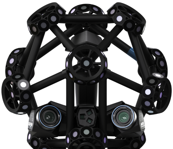
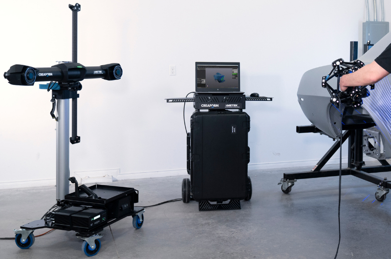
MetraSCAN BLACK+ Elite: 289 × 235 × 296 mm nominal scanner envelope. C-Track: 1,031 × 181 × 148 mm nominal envelope. The R4 models reproduce the black marker cage, twin scanner cameras and long stereo tracking bar from official reference imagery. Mounts, shrouds and interfaces are concept designs, not OEM CAD.
Updated layout and full-cycle simulation preview.
13 min 16 sec · male synthetic narration. R4 walkthrough: purpose, overall dimensions, POC and final differences, every tool, fixture setup, target-cover handling and the complete process. Waiting periods are compressed and are not production cycle-time promises.
Download the MP4 and open it in your device video player.
Proposal and quotation
In-house POC funding envelope
S$441,000 excluding GST
S$386,000 defined POC scope + S$55,000 controlled provisional sums. This is a planning estimate. The user-specified ATEX package is the technical design basis; exact supplier package cost / equipment availability must be reconciled before firm issue.
Permanent final-cell equipment and production implementation are separately priced after POC and design freeze.
Commercial basis · R2 / design update · R4
Detailed budgetary quotation · PDF
Current R4 design update · PDF
R2 background design sheets · superseded arrangements marked by R4 update
Web app: R4-20260923. R2 proposal and quotation remain the commercial baseline; R4 supersedes tool exchange, target protection, cleaning, robot location / travel and C-Track support. Extra R4 tooling / axis / booth adaptation has not been reconciled into the R2 budget. This design update is not a new firm quotation.